The energy monitoring project is ongoing. Meanwhile, we're using the washing line lots because it's "summer" in the UK, which brings the perennial problem of retrieving said washing when it inevitably rains. Neither of us seem to notice when it starts, unless we're outside, standing in it.
Hence the Rain Alert. Plan is
- Obtain water sensor panel and associated I2S adapter with LM393 voltage comparator
- Decide on MCU type (Arduino? No, NodeMCU with ESP8266!)
- Software config
- Generate MQTT alerts which can be monitored by NodeRed
- Calibrate sensitivity pot and software values
- Send alerts if it rains over Telegram to mobile phones, and hence FitBits for intimate reminder (!)
- Hardware packaging and power for externally resident device
So far, I've got as far as 4 above. I was going to programme the ESP8266 myself, but it's just as easy to use the Tasmota software and configure that. It will send MQTT SENSOR messages with all the collected values as frequently as I desire, and I know I can already process those in NodeRed.
<picture of sensor and adapter>
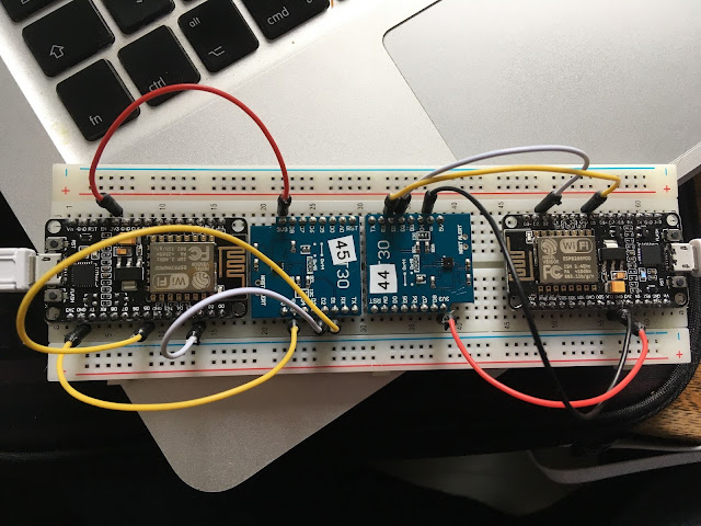
<picture of LoLin NodeMCU "v3" with CH340G USB-serial adapter>
I used the
Tasmota online install web page in conjunction with Google Chrome to flash the unsuspecting NodeMCU (running a 4 year old version of it!) with the Tasmota firmware. A quick read of the online docs, and I defined my own Template, using the Generic (18) as a base. Templates are a convenient way of defining the use of the ESP8266 GPIO ports, which I've never bothered with before, because the Sonoff-Basic(1) usually did what I wanted.
 |
| Tasmota Template Configuration |
Since the adapter has both a digital output (high if voltage difference selected by trim pot is exceeded) and an analog output (presumably the difference of the voltages) I intend to use both for the time being, as it's no harder to do. It will allow me to trim the sensitivity pot in situ. The ESP 8266EX only has a single ADC port, the ESP32 is the one to go for if you have lots of analog sensors. The NodeMCU board also has a voltage divider on the port, because it has a peak input of 1V (versus the 3.3V working voltage - eek!).
The Tasmota software is already doing the business - I could check the pin functions just by connecting them appropriately.
{"Time":"2022-07-05T17:23:51","Switch1":"ON","ANALOG":{"A0":2}}
{"Time":"2022-07-05T17:24:01","Switch1":"ON","ANALOG":{"A0":1024}}
{"Time":"2022-07-05T17:24:11","Switch1":"ON","ANALOG":{"A0":1024}}
{"Time":"2022-07-05T17:24:30","Switch1":"ON","ANALOG":{"A0":1024}}
{"Time":"2022-07-05T17:24:48","Switch1":"ON","ANALOG":{"A0":2}}
{"Time":"2022-07-05T17:24:58","Switch1":"OFF","ANALOG":{"A0":2}}
{"Time":"2022-07-05T17:25:08","Switch1":"OFF","ANALOG":{"A0":2}}
You can see the changing values as I connect/disconnect to 3.3V and Gnd for each of them. Note that ADC A0 doesn't register 0 if it's grounded, and shows 1024 (!) when at 3.3V. This last is a bit weird for a 10 bit ADC... I make that 11 bits!
I've previously messed about with Tasmota, I even modified its code for SHT30 sensors so it could handle 2 on a buss, so I could use a single ESP8266 to take simultaneous temperature measurements of the input/output flows on my boiler. I haven't used it for anything much else, but it is pretty impressive, even complete overkill for simple projects like this, but since it it easily deployed and configured, why the heck not?? I know I can program, let's get the job done.
Now to connect up the adapter and sensor plate and see how they get on.


Comments
Post a Comment