Open Energy Monitor - homegrown emonPi Construction (part 1)
openenergymonitor.org is about "Open source monitoring for understanding energy", and the efforts of some stalwarts who have designed, constructed and had manufactured a number of monitoring devices and supporting software. These are currently based on Raspberry Pi and the Atmel chip used in the Arduino UNO, along with 433MHz radio comms and lots of open source software. The designs are comely open source, to the extent that you could build your own if you were prepared to have SMT PCBs made and so on.
I am interested in monitoring our energy consumption on a more fine grained basis than the 30 minute intervals that BG, in their wisdom, allow limited access to on their website, based on our "Smart" meter (as a SMETS1 device, not smart at all in fact). So the emonPi, with its RPi and an Arduino-stack based monitoring "hat", as a single box device that supports current, voltage, meter pulse sensing and temperature measurement, along with emonCMS, the analysis and stats display package, looked quite interesting. I have a Pi, and an Arduino - could I make them work together??
TL;DR - yes. Read on for more details!
I lashed out on
- two of their DS18B20 temperature sensors, which are encapsulated in a moisture-proof stainless steel jacket
- their AC-AC transformer, used for lowering mains potential to an Arduino-friendly range
- the non-invasive current measuring clamp that is effectively half of a transformer, with the primary being the mains cable
in the interests of needing something to measure, at least to start with. Like all of electronicsLand, they are suffering from parts shortages, and no emonPis are currently available anyway.
Prior to that, I'd downloaded the emonPi SD card image, containing a specific build of Rasbian Lite Stretch, and stuck it on a handy RPi 3 I have. This pretty much worked right away, it's a while since I did it and I can't recall any specific hacks or changes it needed. It runs mostly on Python scripts, which is pretty simple.
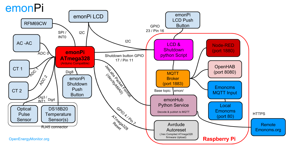 |
| System Overview of emonPi |
Questions:
- The official emonPi uses async comms between Pi and Arduino, which seemed like a PitA. Could I just connect them with USB and have the master Pi power the Arduino and also listen to it on a pseudo-async link?
- 5V vs 3.3V? My Arduino clone can be switched to 3.3V, so that's probably ok, but the official HAT has a 5V supply... do I need one? And if the Arduino is run at 5V, how to interface the GPIO pins without toasting the Pi?
- How much do I need to change or modify before this could work?
Let's have a go...
Firstly, I used an example sketch to test the DS18B20 sensor, which worked pretty quickly and easily. Cool!
I followed the "Load libraries into Arduino IDE" instructions, and also the firmware sketch folder on GitHub. This failed to compile, so I also downloaded the libraries mentioned in the actual source. Hurray! But the lcd_serial.ino part wouldn't compile, as one of its functions was at the bottom rather than the top of the source (!). Modified... compilation achieved!!
Running this on the Arduino didn't give me any errors, and it also didn't give me any output. Bummer. Time to look more closely at things.
I noticed the ONEWIREBUS definition wasn't pointing to the Arduino port I was using (2). Altered that, but probably should have left it at 4. Still no output, and the main loop definitely wasn't Serial.printing things that it was supposed to.
Since I have no intention (yet) of using RF connections when perfectly serviceable WiFi is available, I changed the RF_STATUS flag to false - bingo! That was obviously holding things up whilst trying to get the radio working.
So now the Arduino console was showing a detected temp sensor, no 16x2 1602 LCD (not surprisingly!), and two Current Transformers (!), and a Voltage Transformer(!!). Grounding the relevant pins gave me a 0 value for CT, which was good, but the VT still shows a value. Not sure why yet, and it might be irrelevant soon enough if I get one connected.
The 1602 LCD works by I2C, using a "backpack" which connects to the pins and accepts I2C commands. I picked up one of those from eBay, which didn't take long to arrive. Not sure why this seemed important to me - I just like techy-looking LCDs!
It didn't take long to connect that - basically 4 pins from the Arduino - and before long I was seeing the display light up, declare what it had detected, and stick on "Booting... please wait", in a lovely bright high-contrast display. Hmm. Ah, yes, the RPi shares the I2C bus and produces a lot more stuff on the display - in fact, a pushbutton allows for the display to be changed! Gotta do that...
Connected the RPi to the Arduino, which provided power and potentially a data connection over USB. Examining the emonPi code, it appears that it's emonhub that collects the data from the Arduino and its RF-connected sensors. The Arduino sends the data in a specific format (JEE packets) to the RPi over async on data ports 0/1, so the emonhub monitors the standard RPi async port i.e. /dev/ttyACM0. Took me a while to work out that this port is specified in emonhub.conf, tucked away in /opt/openenergymonitor/emonhub/conf/emonhub.conf. I edited this as shown below to point at the nominal USB async pseudo-port, and restarted everything.
[interfacers]
### This interfacer manages the RFM12Pi/RFM69Pi/emonPi module
[[RFM2Pi]]
Type = EmonHubJeeInterfacer
[[[init_settings]]]
# com_port = /dev/ttyAMA0
com_port = /dev/ttyACM0 # Modified to use USB serial port hopefully
Success! Logging into the emoncms web interface (emonpi.local) and looking at the emonhub page, the log showed 10 second updates being received from the Arduino - result. I had the temp sensor connected, so was able to use the Graphs page to look at a notional graph of temperature over time. Let's see if we can get the shared LCD working, from both Arduino and RPi.
In order to prevent RPi GPIO cremation, I switched the Arduino to 3.3V, before connecting the RPi I2C ports to the same pins as the Arduino. A reboot - it works! Also, by connecting the GPIO 23/Pin 16 briefly to +ve, the display switches mode etc. Excellent. Except the display was really dull and hard to read, with no contrast to speak of, and turning the contrast pot on the backpack made little or no/worse difference.
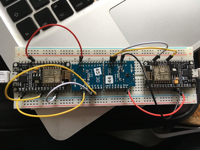
Er, it's 5V vs 3.3V, stupid! The 1602 is meant to run at 5V, especially the contrast/brightness inputs. So I got a separate I2C backpack off eBay, and separated the 3.3V from the 5V - Arduino runs at 3.3V, but I use the 5V output to power the 1602 separately from the backpack, which runs at 3.3V. All on a breadboard of course. Success! Lovely bright high contrast LCD, RPi & Arduino not releasing any magic smoke. As you'd hope, but hey.
Now to sort the other V and C sensors...
What will I do with this? Don't know yet, it's a journey.

Comments
Post a Comment